Making a DIY Heart Rate Sensor
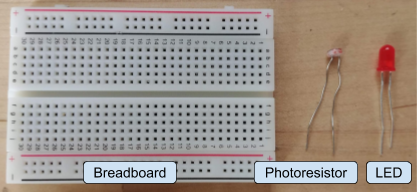
Materials List:
| Description | Circuit Element | Photo |
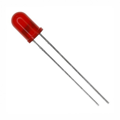
| LED (Light Emitting Diode) |

|
|
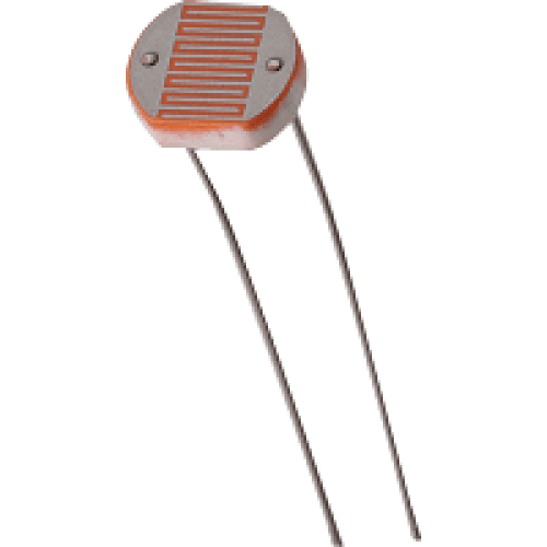
| Photoresistor |

|
|
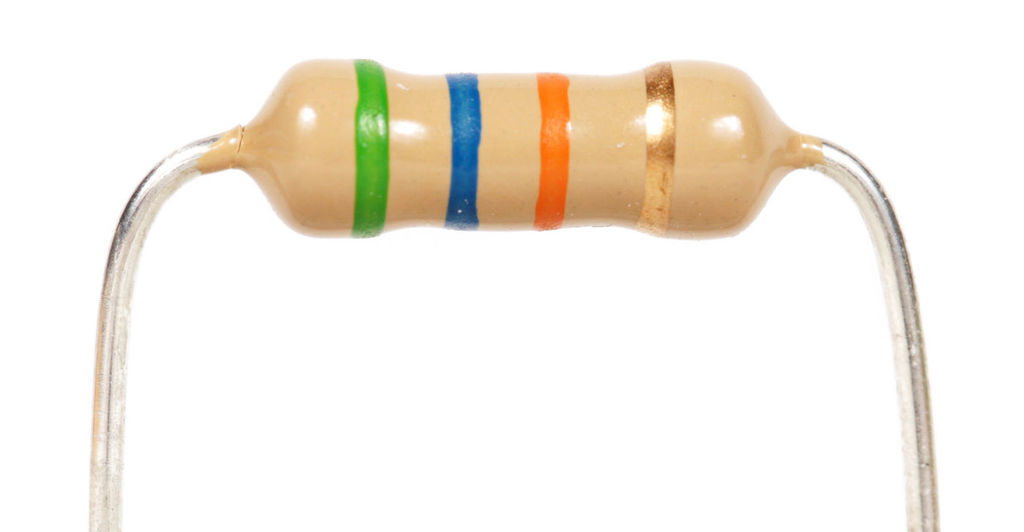
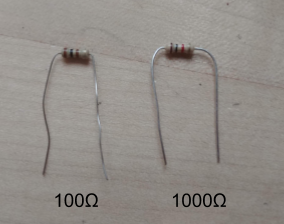
| Resistors (100 Ohm, 1000 Ohm) |

|
|
| Breadboard |
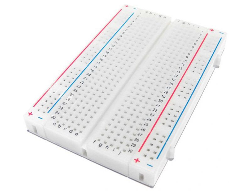
|
|
| Jumper Wires |
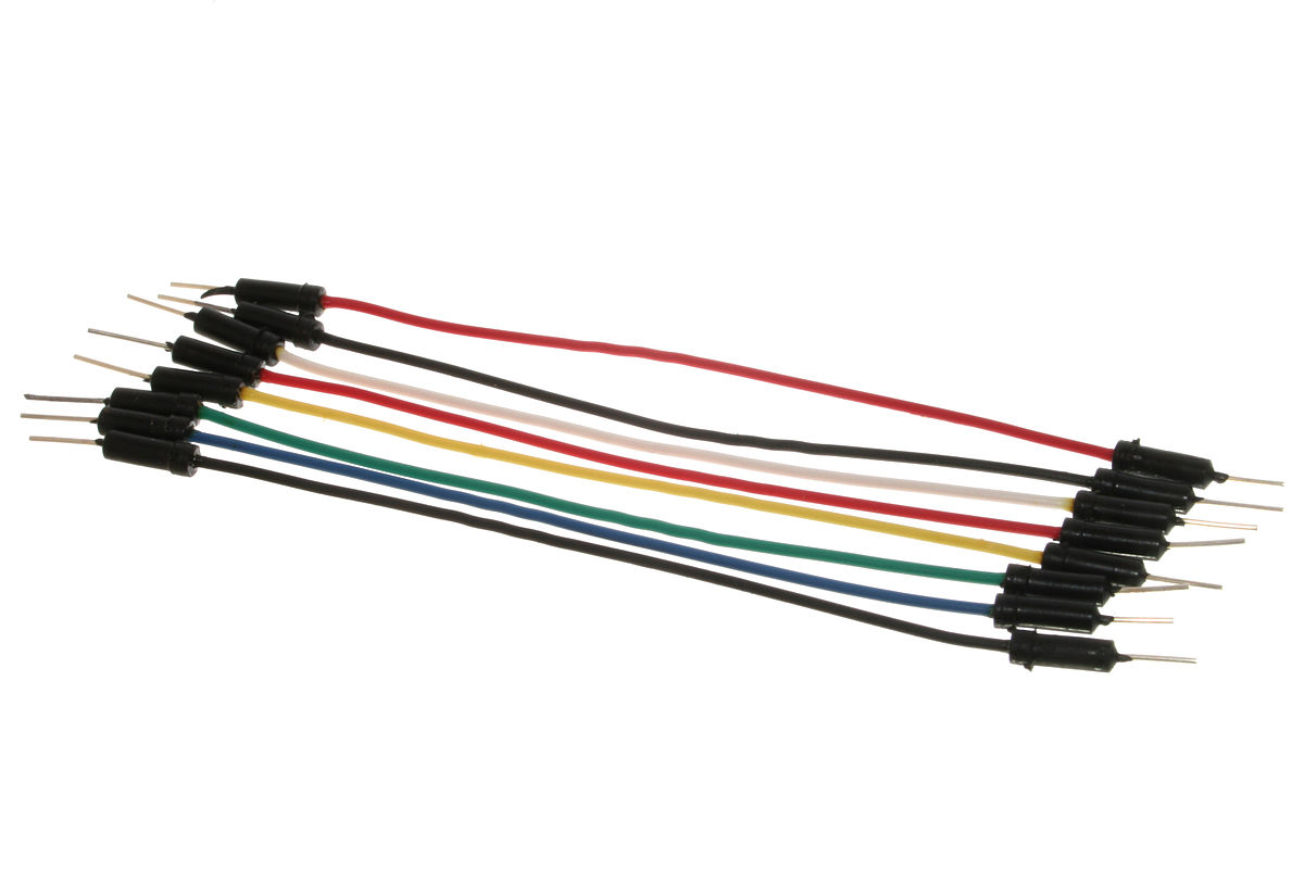
|
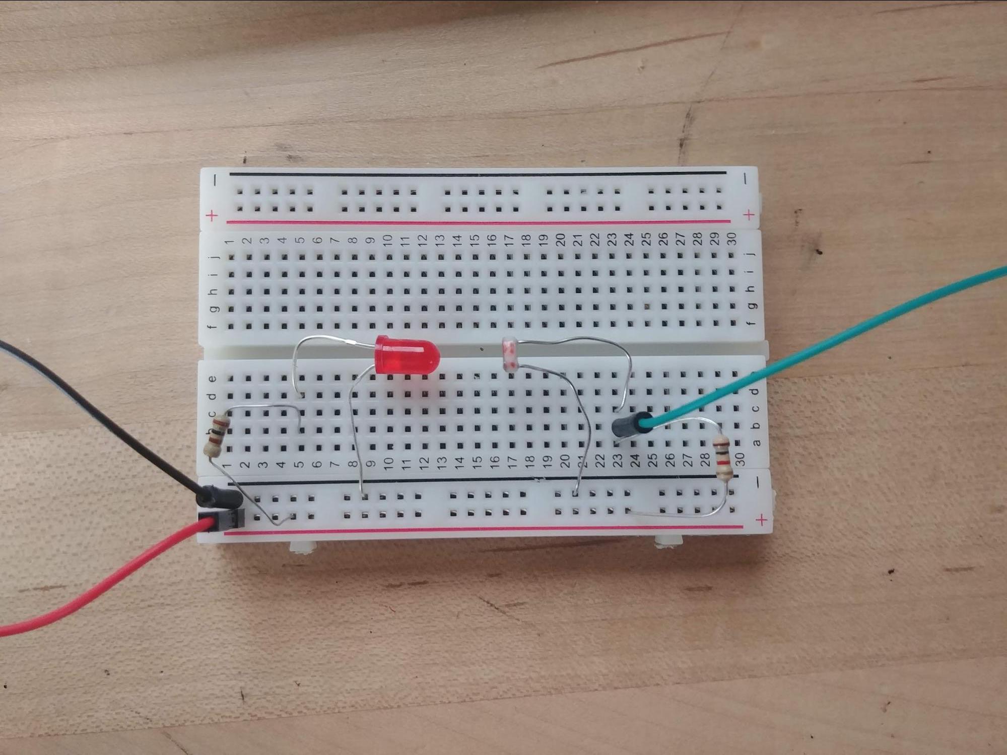
Assembly Overview
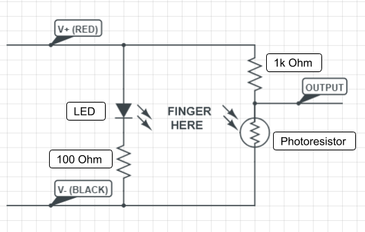
Circuit Schematic
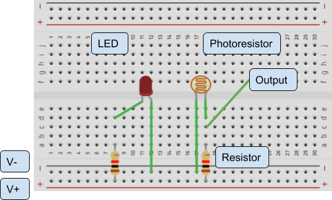
Breadboard Layout
Step-by-step Assembly Instructions:
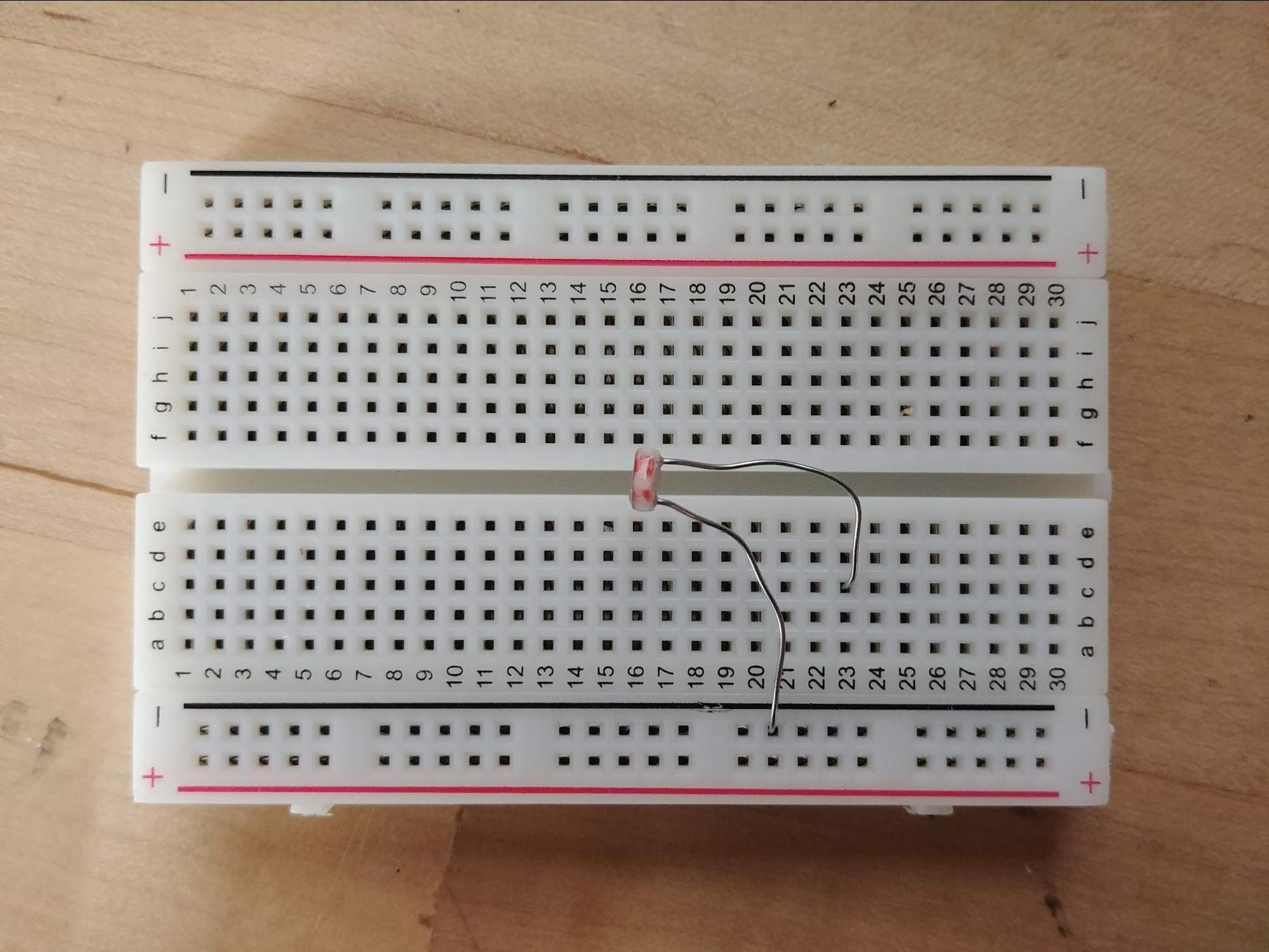
Step 1: Setting up the LED and Photoresistor
What you'll need for this step:
-Breadboard
-Photoresistor
-LED
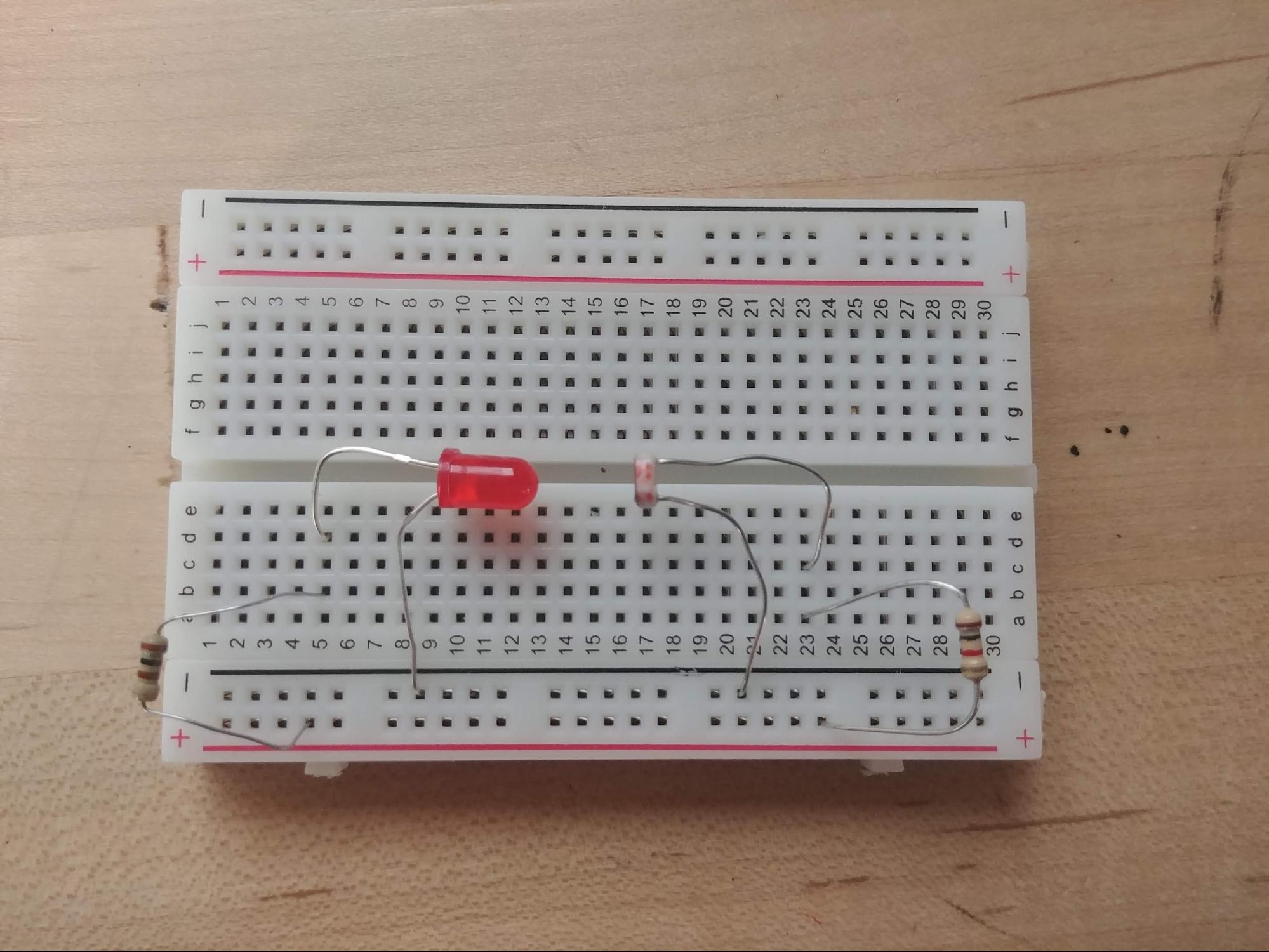
Insert the Photoresistor as shown to the left, with one leg in the negative (black) power rail, and one leg in one of the numbered rows in the middle of the breadboard. Make sure the two legs are not touching and that the photoresistor is facing the left side of the breadboard.
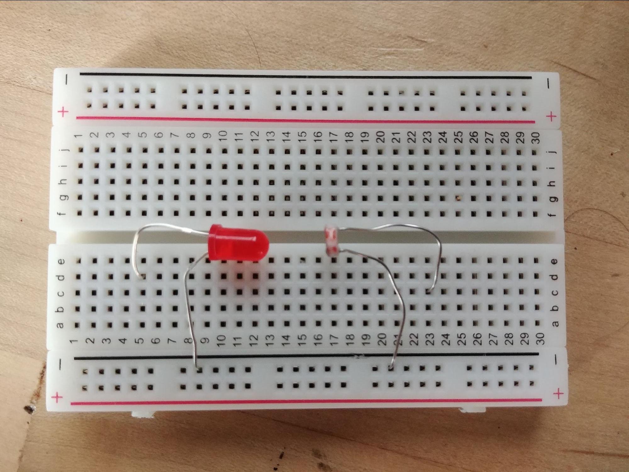
Next insert the LED as shown facing the photoresistor. Unlike the photoresistor, the LED must be inserted with the shorter leg (the negative side) on the negative (black) power rail and the longer leg in one of the numbered rows in the middle of the breadboard.
Step 2: Resistors
What you'll need for this step:
-100 Ohm (Ω) Resistor (Brown-black-brown)
-1000 Ohm (Ω) Resistor (Brown-black-red)
Insert the two resistors as shown below. The 100 Ohm resistor goes between the longer leg of the LED and the positive (red) power rail. The 1000 Ohm resistor goes between the photoresistor and the positive (red) power rail.
Step 3: Jumper Wires
The final step involves inserting the cables for the two power rails and the sense cable. The red and black power jumpers go into the red and black power rails, and the third jumper cable connects to the output of the photoresistor, specifically the connection point between those two components, as shown to the left.