pH Probe Assembly
Step 1:
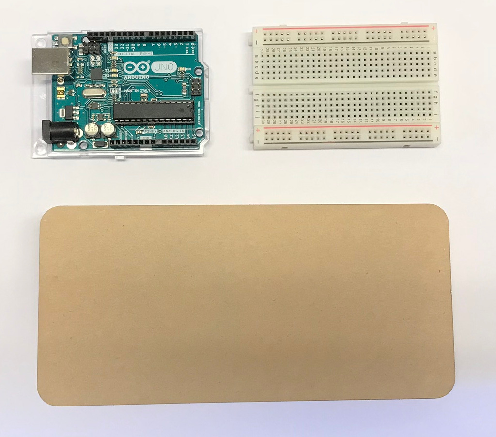
Start with the Arduino Uno (top left), breadboard (top right), and *acrylic sheet (bottom).
*The acrylic sheet is optional.Step 2 (optional):
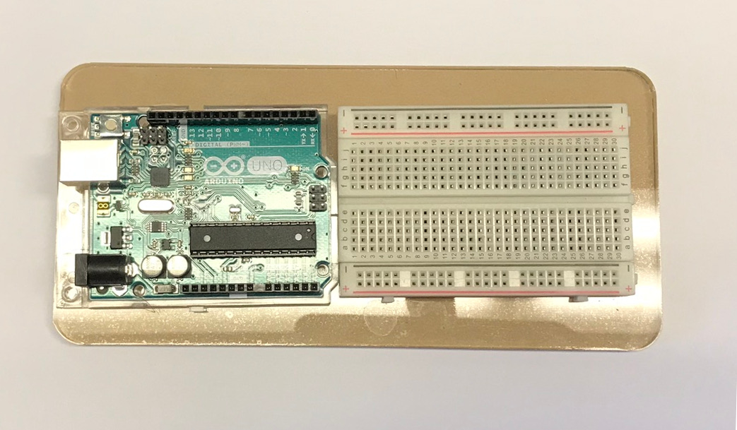
Attach the breadboard and Arduino Uno side by side onto the acrylic sheet as shown, using double sided tape.
Step 3:
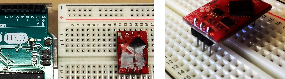
Insert Chip 1 (red pH chip) onto the breadboard. You could do that in different ways, but to make things easy use the following: Insert the bottom three pins (with the "pH EZO" label) into 12,13,14 on Row D. Insert the top three pins into 12,13,14 on Row I.
Step 4:
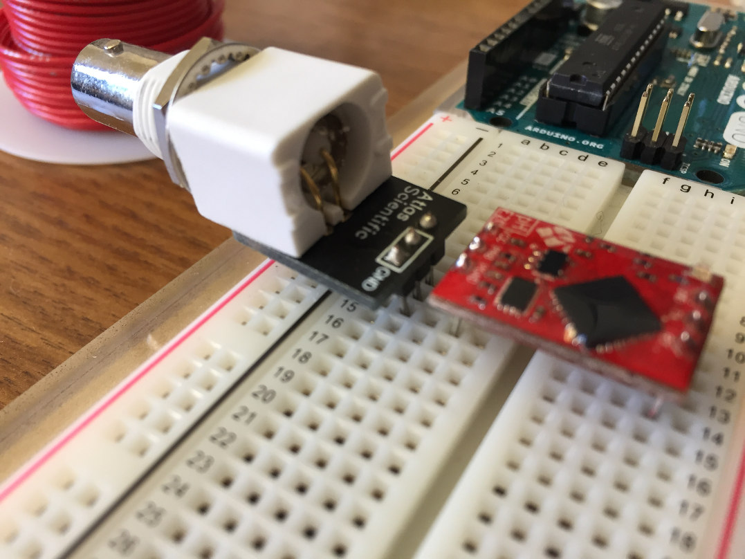
Insert Chip 2 (Atlas Science chip) directly below Chip 1, leaving room for a row of wires between the two chips. Check to make sure the pins from both chips are up vertically on the breadboard. That is to say, put the three pins into 12, 13, and 14 on Row B.
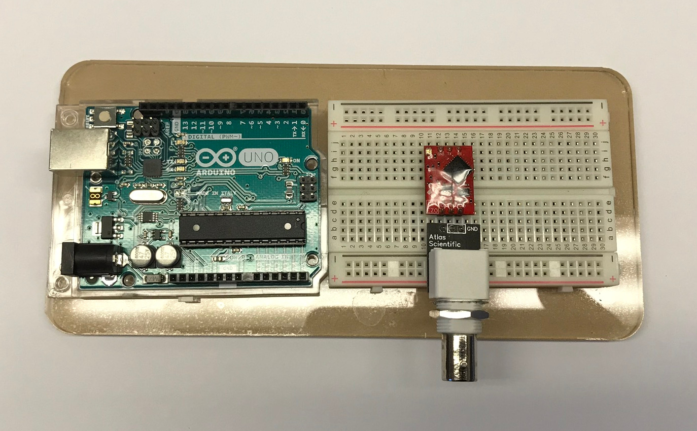
Step 5:
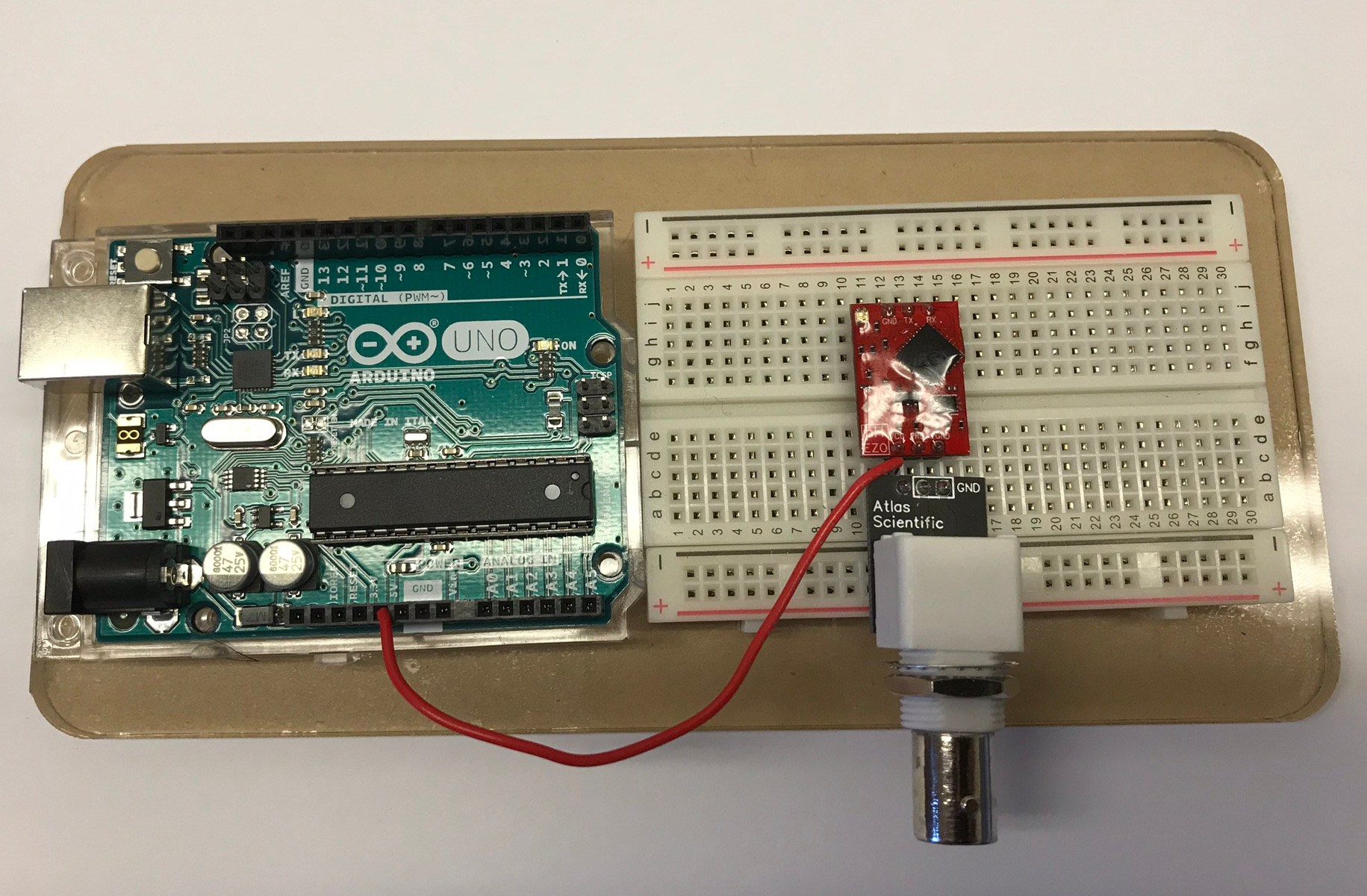
Cut some wire, strip the insulation off of each end, and connect the 5V on the Arduino to the VCC on the breadboard (Row C, Column 12).
Step 6:
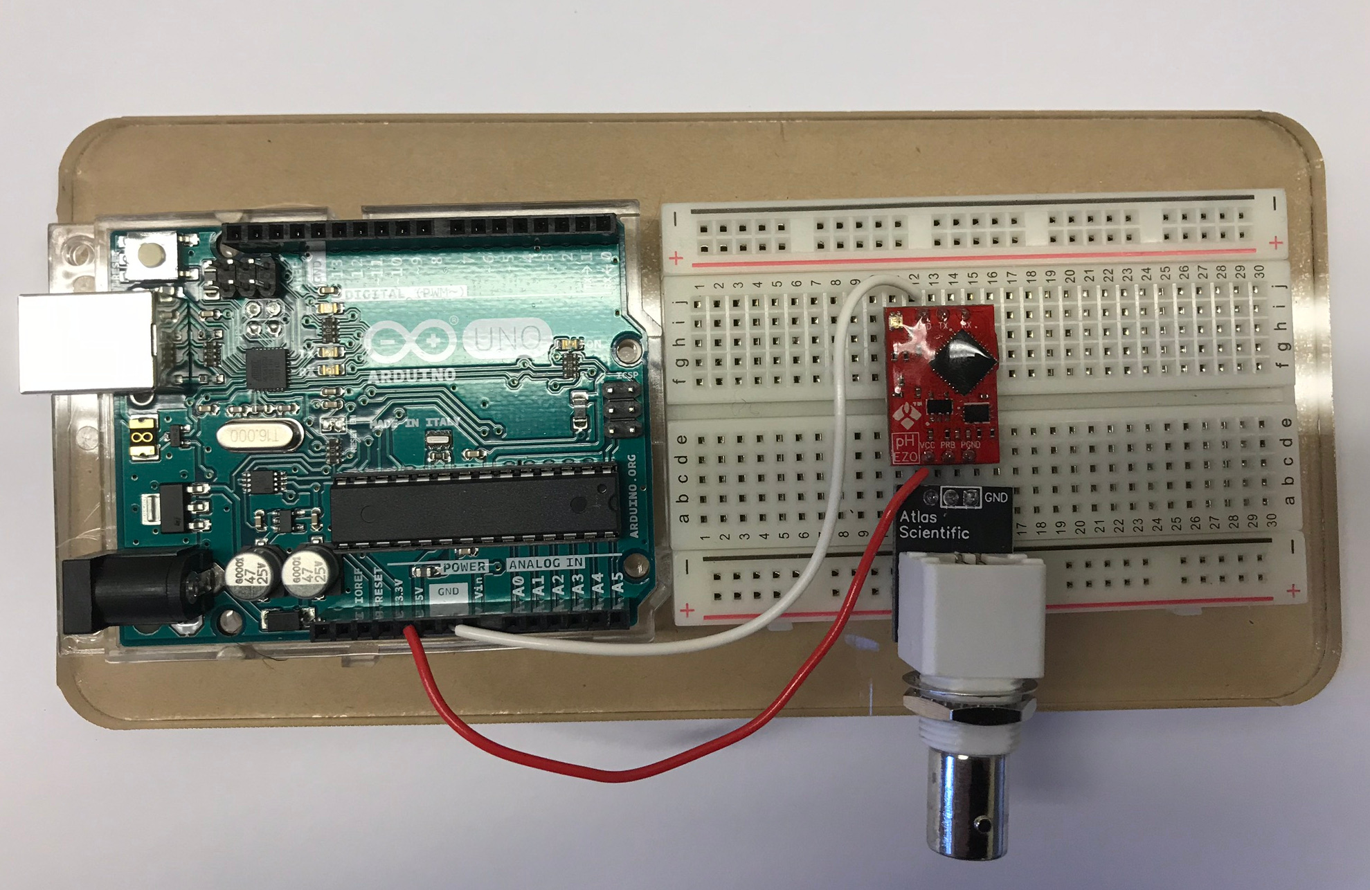
Cut some wire, strip the insulation off of each end, and connect the ground (GND input) on the Arduino to the ground on the breadboard (Row J, Column 12).
Step 7:
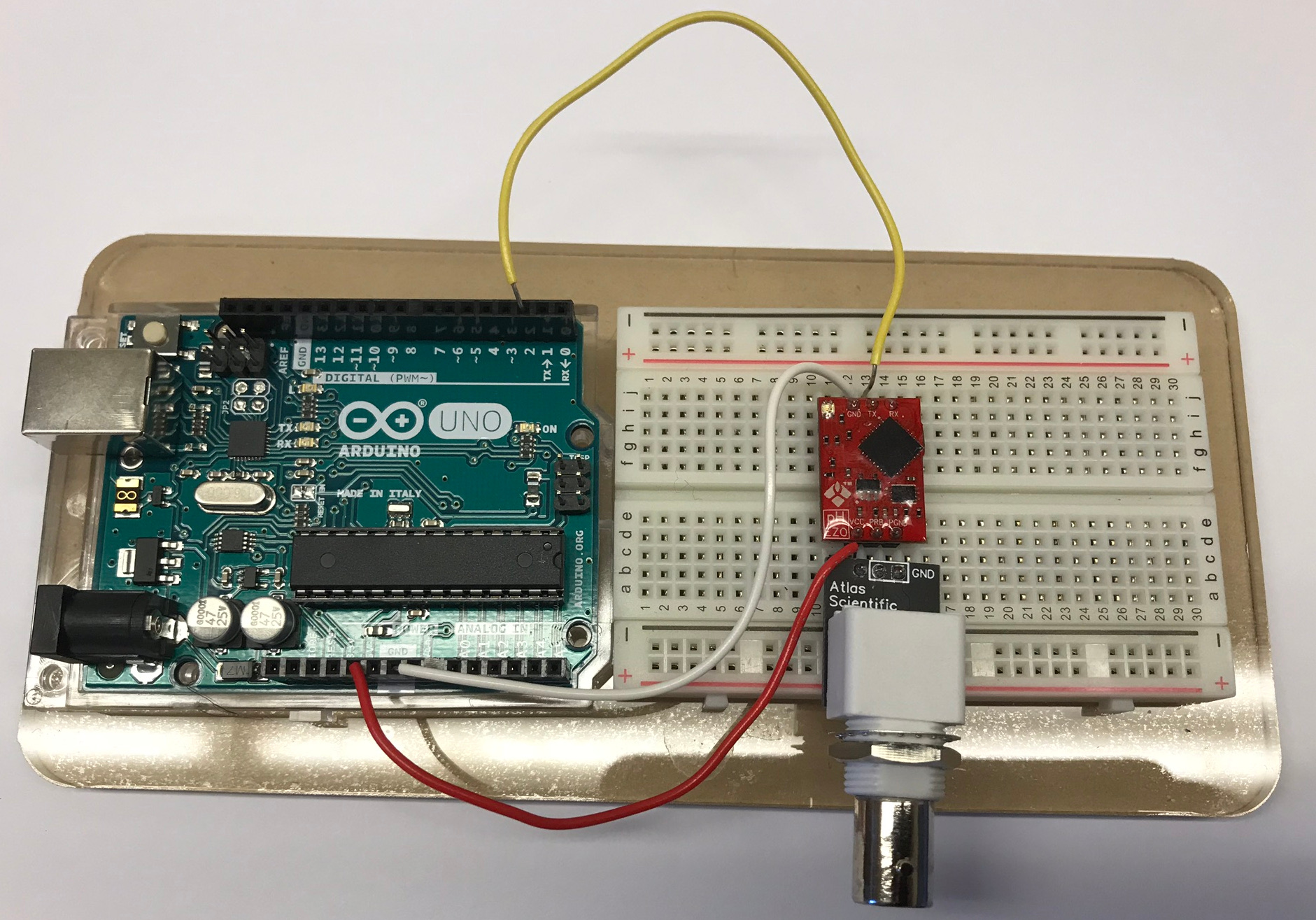
Cut some wire, strip the insulation off of each end, and connect Input 2 on the Arduino to the TX on the breadboard (Row J, Column 13).
Step 8:
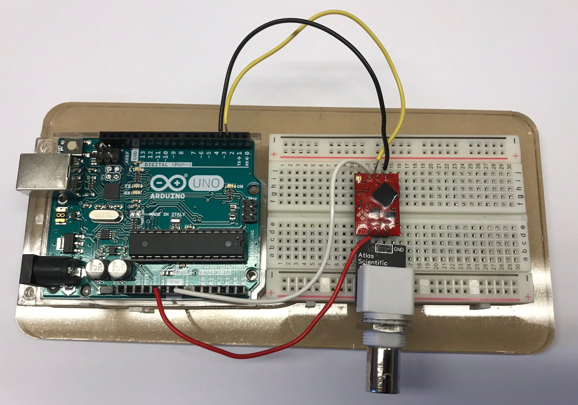
Cut some wire, strip the insulation off of each end, and connect Input 3 on the Arduino to the RX on the breadboard (Row j, Column 14).
Step 9:
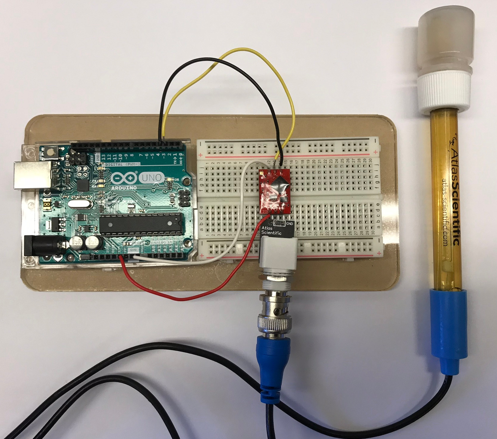
Connect the pH probe to Chip 2 on the breadboard with the BNC connector. Align the pin, push the collar on and twist. Congrats! You should now have a finished pH probe. Click here to move on to calibration.