DIY Jump Plate Tutorial
The purpose of this project is to develop a DIY vertical jump measurement platform. The platform can be used in lots of different ways. By building it, students can learn more about engineering, physics, computing and other STEM topics. By using it, you can improve your athletic performance, create little mini-games with your friends, and conduct scientific inquiry in Sports Science and Biomechanics.
The basis of the measurement is to use the amount of time you are off the plate, "delta t" (Δt). The gravitational constant, g, determines the height (hf) of the jump of any particular duration will be. This equation is :

G is the gravitational constant, which is 32.2 (if you are using feet). So if you are off the plate for 0.5 seconds, the square is 0.25. Now just multiply: that is 32.2* 0.25/8 = 1 foot. The software below will allow you to graph the amount of time off the plate. Then you can plug that into the equation.
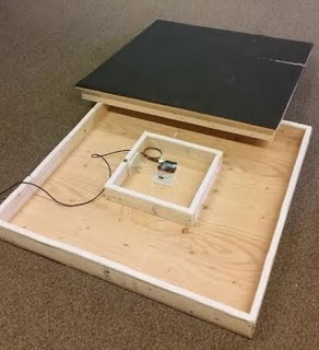
To construct a DIY Force Plate as pictured below, follow this tutorial. The total project was constructed from materials purchased from Home Depot for a total of $51.91.
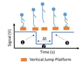
The vertical jump platform determines the vertical jump height of subjects by measuring hang time (Δt) and calculating the jump height that would allow for that flight time.
Final Contact Plate Construction
|
Materials |
Quantity |
Cost |
Total Cost |
|
15/32” 4'x8' Plywood Sheet |
1 |
$18.57 |
$18.57 |
|
1”x3” beams |
4 |
$1.74 |
$6.96 |
|
2” Wood Screws (50ct) |
1 box |
$5.58 |
$5.58 |
|
¾” Nails (50 ct) |
1 box |
$2.98 |
$2.98 |
|
Handles |
4 |
$2.50 |
$10.00 |
|
1 ¼” Nail on Felt |
1 |
$2.78 |
$2.78 |
|
Rubber matt |
2 |
$2.52 |
$5.04 |
*Note: the nail on felt was later replaced with large green rubber bands
Tools:
-
Hand Saw
-
Power Drill
-
Pencil
-
Straight Edge
-
Silver Sharpie
-
X-Acto Knife or Scissors
Steps
1. Purchase materials at Home Depot (or any home improvement store.) Have an employee cut the plywood into the dimensions shown below. Also, if you do not have access to a table saw, have an employee cut the plywood and wood beams.
2. Cut the wood according to the following dimensions:
a. Plywood:
i. Two 3'x3' sections. (Save the rest as scrap because you pay for the entire sheet anyways. It can be used for a project in the future.)
b. Four 1”x3” beams:
i. Four pieces of 35.25”
ii. Four pieces of 34.5”
iii. Four pieces of 11.25”
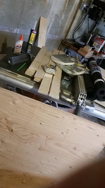
Materials Gathered & Wood Cut
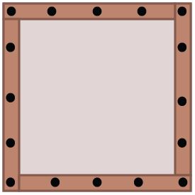
3. Once all the materials are gathered and wood is cut, the assembly begins. On one piece of plywood, draw a 1'x1' box in the middle on both sides using a pencil and straightedge. Measure 1' from each edge, and it will be centered.
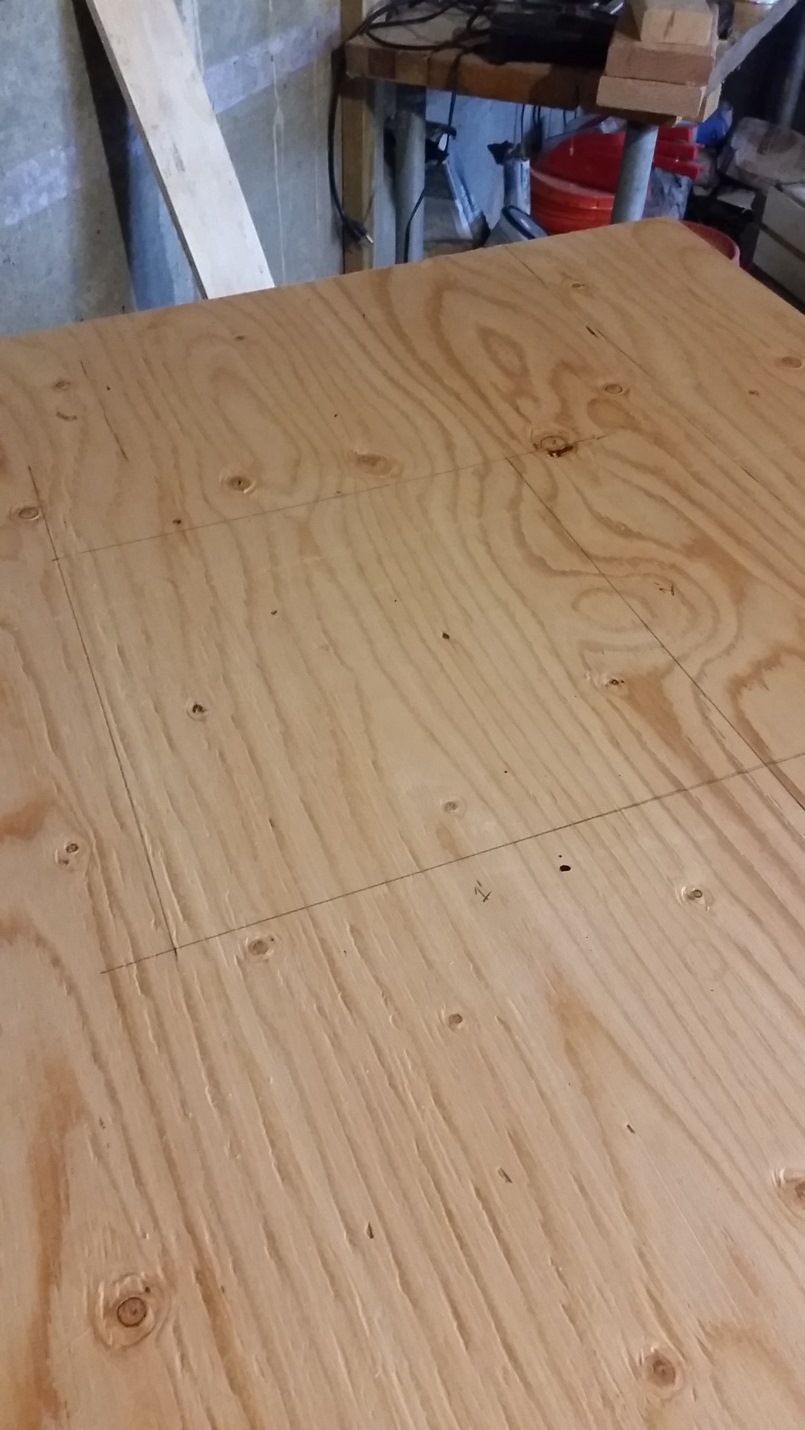
1'x1' Box Drawn
4. With the same piece of plywood and the four 35.25” beams, layout the perimeter. This will be the frame for the bottom of the contact plate. (It does not matter which side is up or down for this step.) Lay the plywood on the ground, and place the beams around the edge to check the fit of each cut. The beams should fit to the edge of the plywood, without overhang. If there is overhand, cut the pieces to fit.
5. Take the piece of plywood, and each piece of 35.25” beam (one piece at a time), and drill pre-set holes through the plywood into each beam along the edge for the perimeter. (This allows the screws to go into the wood without splitting it.) Have one person hold the beam into the plywood and the other one drill. This is done easily while holding the beam to the plywood in the air. Approximately four screws will go into each piece.
Hole Positions for Frame
6. Once the preset holes are drilled, drill the beams into the plywood from the plywood side using the same holes and 2” wood screws.
7. Drill each end together with one screw from each beam going into the connecting one at the corner.
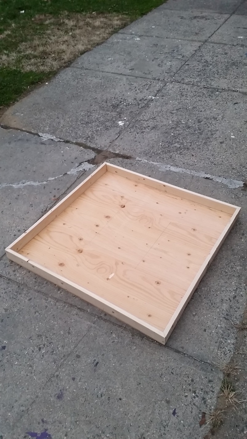
Bottom Frame
8. Taking one of the 11.25” pieces, drill a hole through the side for the electronics cord to fit through. (Approximately 1” diameter.)
9. With all four 11.25” pieces, also drill pre-set holes around the sketched box in the center. Have one person hold the beam to the drawn box, piece by piece, and have the other drill the holes. The beams will go onto the same side as the other beams. This new, inner perimeter box will hold the electronics.
10. Drill the 11.25” beams onto the plywood using the 2” wood screws.
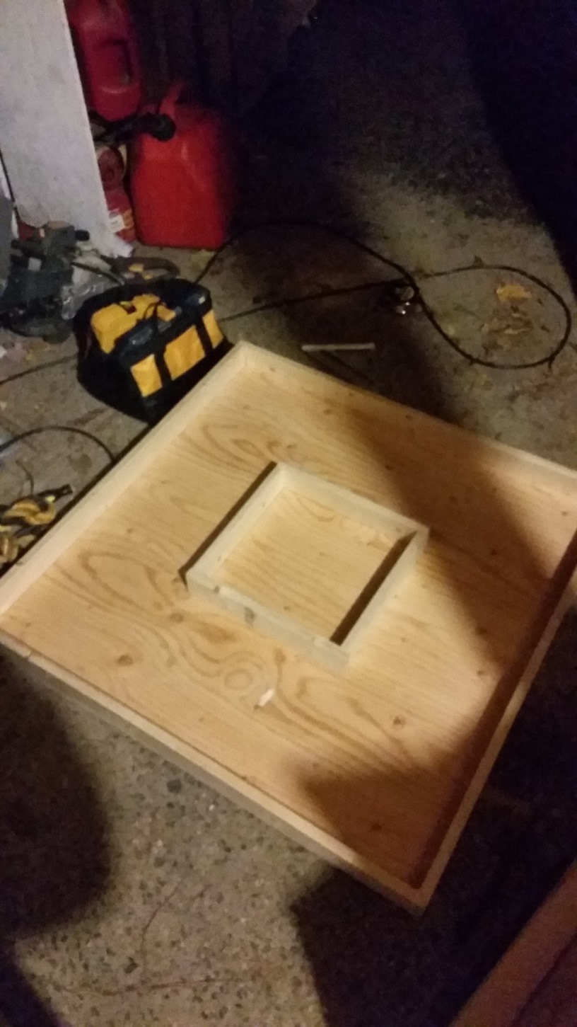
Inner Frame
11. Take the other piece of plywood and the four 34.5” pieces. (This sheet would act as the top of the contact plate - as a lid that sits inside the bottom.) Set the beams inside the bottom part of the contact plate (that you just constructed) against the perimeter of the outer beams. (This is to align the top to the bottom to fit as a box.)
12. Set the other piece of plywood on top. Make sure the inner beams do not move during this, and the top plywood aligns with the bottom. This is very important for the overall fit of the contact plate.
13. Measure and mark from the edge of the top piece plywood in 1.125”. Draw this new perimeter around the edge.
14. Drill the preliminary holes from the plywood into the inner beams. This will be done with the top piece of plywood on top of the bottom box with the inner perimeter beams in place.
15. Drill the 2” screws into the holes. Drill one or two screws into each beam to check the fit and alignment. Take the top off the bottom, and each piece should be fully attached with no screws showing or sticking out. If there are any that did not fully make it into the beams, remove them with the drill, and re-drill the holes.
16. From here, the main construction of the contact plate is complete, and the remainder of the assembly does not need to take place in a shop (this part of our plate was constructed in an apartment kitchen.) Lay the top and bottom pieces of the contact plate down with the plywood side up (sitting on the frame.)
17. Lay the rubber matting on top of the plywood, and use a silver sharpie to draw a line along the edge of the plywood to cut the mat.
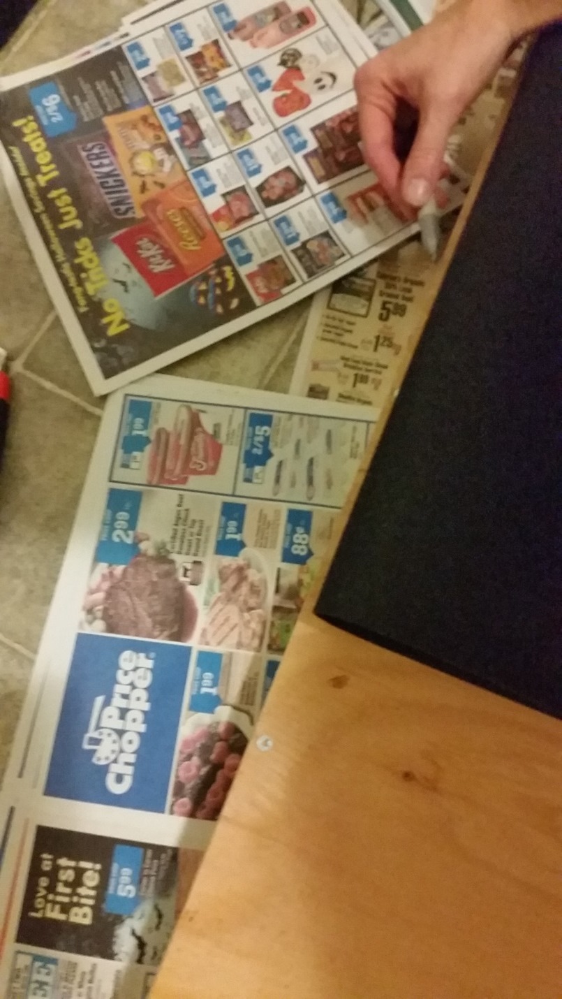
Using a Silver Sharpie to Cut the Mat
18. Cut the rubber matting to fit the top of each piece of plywood.
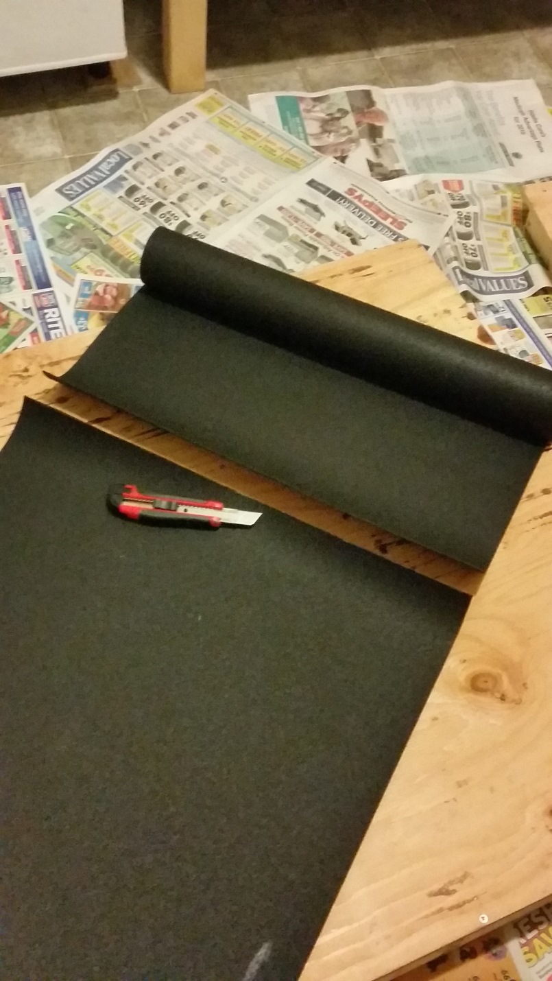
Using an X-Acto to Cut the Mat
19. With pieces of the rubber matting to fit each piece, nail the mats down to the top of each plate with the ¾” nails. (Note, these nails will poke through the bottom of the plywood so it's suggested you also hammer the underside down to prevent getting cut while handling the contact plate.) *Note: the nail on felt was later replaced with large green rubber bands for durability.
20. Drill holes for the handles on the outside beams of the top piece, and screw each handle in to attach it.
Coding
The following code is used in Arduino to receive information from the circuit. In addition, Processing is used to gather the data from the Arduino. From this data, Excel is then used to graph the data. Both Arduino and Processing can be downloaded from their websites below:
Arduino: https://www.arduino.cc/
Processing: https://processing.org/
The following code can be pasted into Arduino and contains the Processing code commented out within it. To utilize the Processing code paste it into the Processing program and remove the “/*” before “import processing.serial.*;” at the beginning of the Processing code and the “*/” from the very end of the code. Both codes contain text throughout instructing proper implementation:
Software
Hardware
This part of the project will connect the contact plate to the software. This will be creating a circuit for the sensor, resistor, and Arduino.
Materials:
1. Connect the Arduino cord to your computer.
2. Open Arduino.
3. Open Processing.
4. Copy the above codes to their respective programs.
5. In Arduino, go to Tools --> Port --> select the port that says Arduino in the name.
6. Press the 'check' to verify.
7. Press the 'arrow' to upload.
8. Go to Tools --> select Serial Monitor and the data will begin to generate on screen.
9. To see a live graph of the FSR value close the Serial monitor, open Processing and click run.
- Wire
- Sensor - found here: http://www.adafruit.com/products/166
- Chip OpAmp chip - Texas Instruments TLV2404IN - https://store.ti.com/TLV2404IN.aspx
- 2 Breadboards
- Wire Cutters
Construct the circuit as shown below:
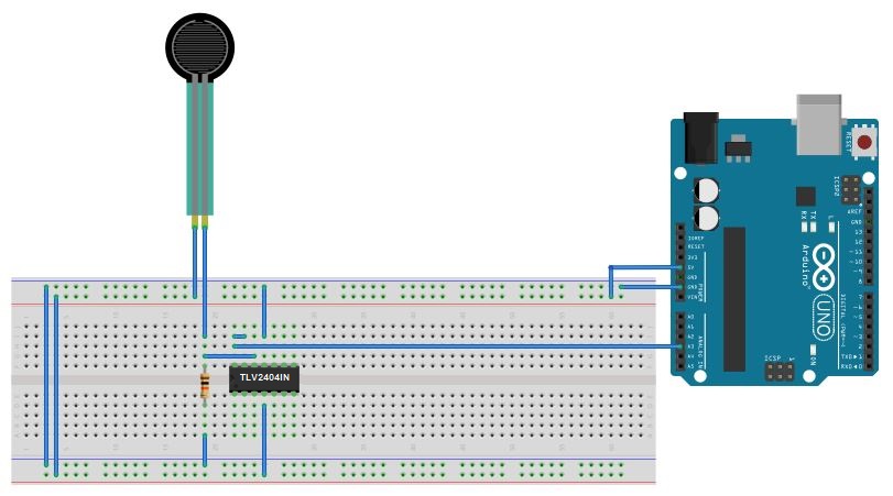
Schematic of Arduino with Breadboard Sensor Setup
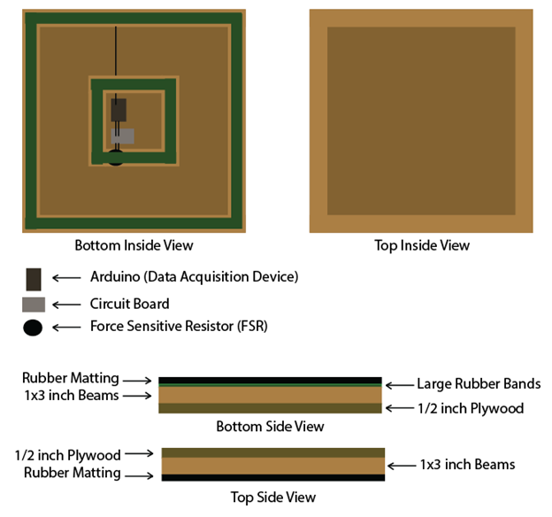
Schematic of Top and Bottom View of the Contact Plate