2. Connecting Wires
For multi-strand wire, twist the tiny strands together into one bunch first. Use multistrand wire for long flexible connections, like power supply to a switch. Do not use multistrand to connect to the protoboard.
Protoboard and LED Basics
By the end of this lab you should be familiar with:
Find the people in your group with the least experience with electronics and help them do it, rather than do it for them.
For multi-strand wire, twist the tiny strands together into one bunch first. Use multistrand wire for long flexible connections, like power supply to a switch. Do not use multistrand to connect to the protoboard.
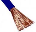
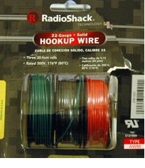
Use solid core, 22 gauge “hookup” wire anytime you are connecting to the protoboard. Use electrical tape or (better for permanent) heat-shrink tubing over wire joins to prevent shorts.

If you need the wire to be permanent (imagine an hour of debugging only to find that your circuit didn't work because a wire accidentally disconnected itself) then use this “western union” twist.
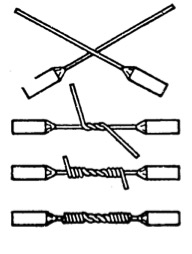
For even better strength, you can start winding the wire back in the other direction, towards the center, after a few winds. Solder will help the mechanical strength as well, but the purpose of solder is to make an electrical connection: the connection should not depend on the solder to prevent mechanical stress from undoing it. To keep wires from accidentally pulling out of the bread board, use tape or weights to secure them to the table, or use a separate base of wood, cardboard or plastic.
If you have never soldered before, now is your opportunity to do so. There is a nice guide online here. Just practice connecting wires. Never apply solder to an Arduino or other delicate components that can burn out from the heat.
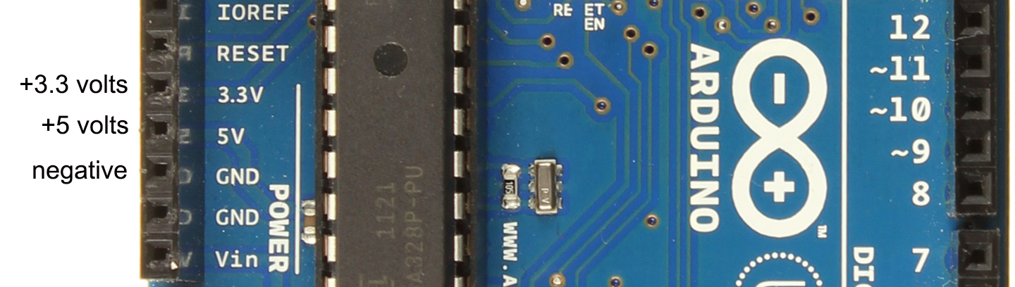
To supply power to your protoboard you can find a power supply in our cabinet, but an even easier source is to just plug in your Arudino via the USB cable to your computer. The Arduino has +5, +3 and ground (negative) connectors that take the same 22 gauge wire as your protoboards.
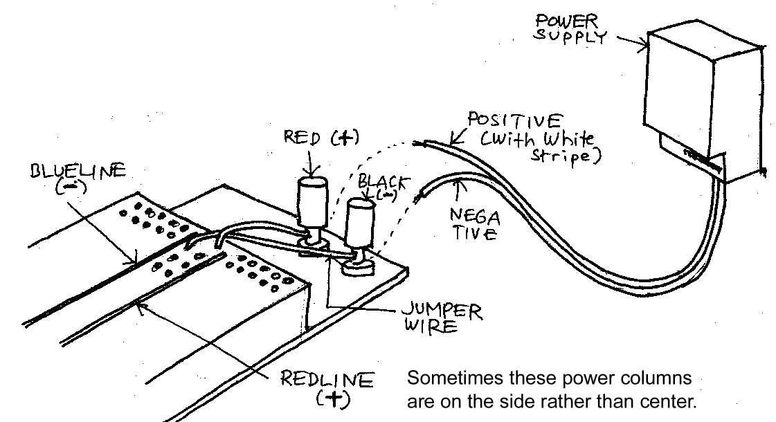
If your use another power supply, and it does not have solid core wire connectors at the end, connect them now. Use a multimeter to test the polarity and color-code the wires: black or green as ground (negative), red, white or yellow as positive. Take care not to nick the core when you strip off the insulation. Solder the join. When soldering, make sure the tip is clean - you can use wet paper towel or sponge to clean it when it is hot—then “wet” the tip with a little solder. Heat the wired joint: ideally you want to have the wire melt the solder and not the iron.
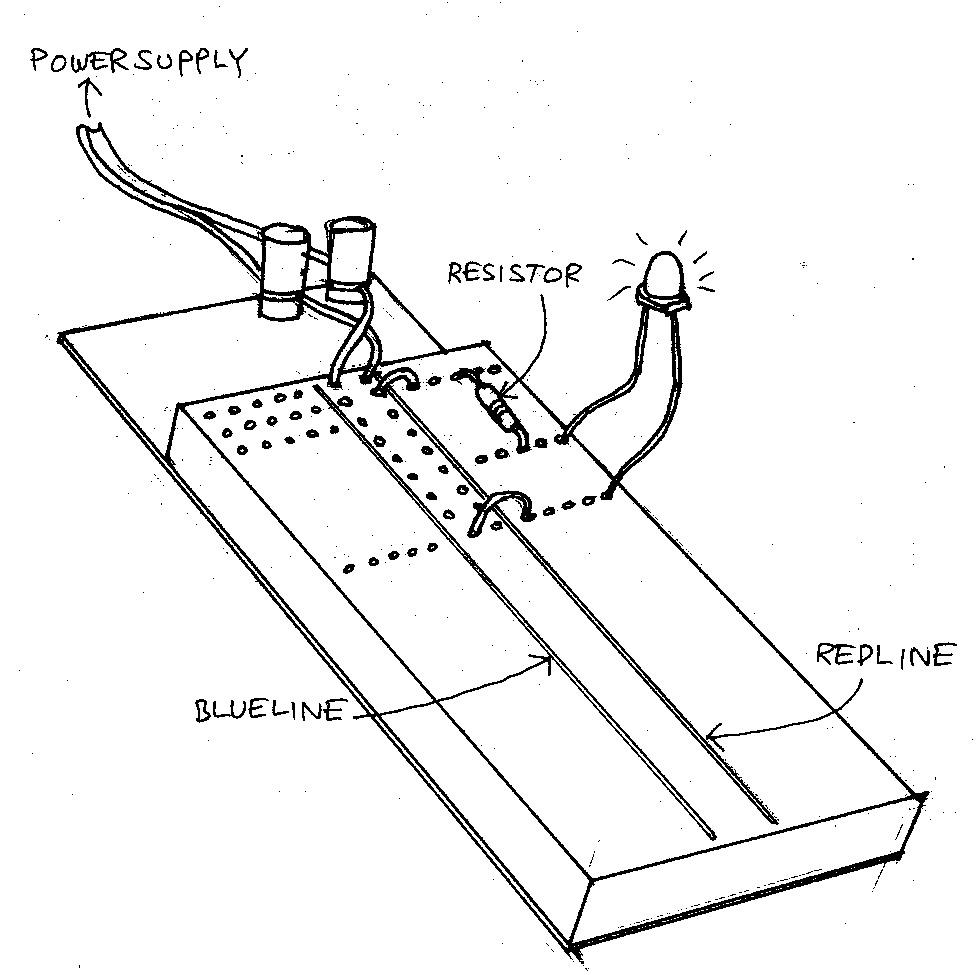
Note that the holes in horizontal rows on either side of the center are connected to each other, but the center keeps the rows on either side disconnected. The holes in each vertical colored column (usually red and blue) are all connected as well, so they can deliver power. Some power supplies have a polarity switch, so test it with a multimeter to be sure you know which is truly positive. Always color-code wires when possible.
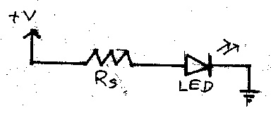
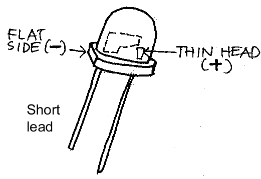
Light-Emitting Diodes (LEDs) are relatively rugged, long-lived optical sources. They must be connected with the correct polarity (longer lead is +).
Because LEDs are current dependent, it is usually necessary to protect them from excessive current with a resistor. You can determine the exact resistance that would be optimal with the formula below, but it usually works fine to just use something between 200 to 300 ohms. It doesn't matter which side you put it on.
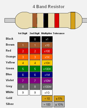
Resistors are color-coded, usually 4 colors. From the left, the one shown below is brown, black, red, silver. The first two are consecutive digits: brown=1, black = 0, so together that reads 10. The third is a multiplier: red=100. So the resistance is 10X100 = 1,000 ohms (“1K ohms”). The last band is usually gold or silver, and gives the tolerance (how accurate the value is: 5% gold, 10% silver).
The chart for all the colors are below. If you want to check to make sure you have the right value or color sequence, you can use one of the handy applets that are available online for that purpose. There is also a 5-band system that has a 3rd digit, and a 6 band system that includes temperature tolerance, but you probably will not encounter those in our studio.
When using resistors it's a good idea to check with the multimeter, and you can also use an online calculator.
If you want to really geek out you can calculate the exact value with the formula:
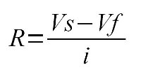
i = LED forward current in Amps (found in the LED datasheet, around 0.01amps)
Vf = LED forward voltage drop in Volts (found in the LED datasheet, typical values below)
Vs = supply voltage
V LED
| Green | 2.2-3.0 V |
| Yellow | 2.2-3.0 V |
| Orange | 1.8-2.7 V |
| Red | 1.6-2.0 V |
For example, (9volt supply - 3.0 volt drop)/0.01amps = 600 ohms
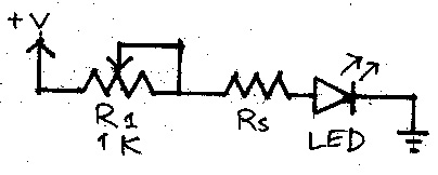
You can try with different combinations of LEDs and switches, a variable resistor (potentiometer), etc. Remember to put a series resistor between potentiometer and LED. Check off your name at this doc.