Flex and Pressure Sensors
How-To: Flex and Pressure Sensors
The flex sensors and pressure / force sensors work in similar ways and are therefore easy to interchange with each other. This quick how-to will show you how to hook up either sensor as well as introduce you to basic coding functions in order to help you start experimenting.
Quick Background
Resistors:
Resistors are electrical components that serve to limit the flow of electricity through a circuit by consuming power. The value of a resistor, called the resistance, is measured in Ohms and can vary in size. The larger the resistance, the more power it consumes..Usually, there will be four colored strips which will represent the value of the resistor. The first two strips will be digits, the third will be an exponent of 10 by which the first two digits are multiplied by, and the last strip will tell you the tolerance. The last strip is the only strip that can be silver or gold. The chart below briefly illustrates this and demonstrates which color represents which digit.
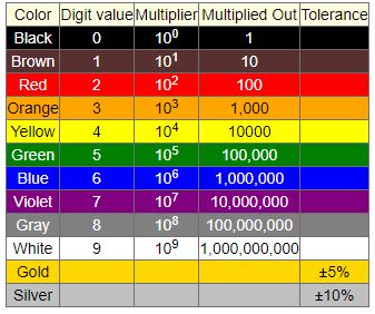
Figure 1: Resistor color code chart
(https://learn.sparkfun.com/tutorials/resistors)
Ohm's Law:
Ohm's Law states that the voltage measured across a circuit or electrical component is directly proportional to the product of the current (I) and resistance (R).
V=I*R
Voltage divider:
A voltage divider is a specific type of circuit that divides the input voltage across the electrical components in the circuit. A voltage divider has two resistors connected to the input and each other in series. Series just means everything lies across along a single path. An measurement of output voltage is then taken in between the resistors as shown below.
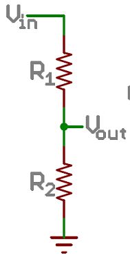
Figure 2: Voltage divider schematic
(https://learn.sparkfun.com/tutorials/voltage-dividers)
Hardware
As we mentioned before, flex sensors and pressure sensors act as resistors. More specifically, they are variable resistors which means their value, or resistance, can change which is why they provide readings that change. In order to use these sensors, we will create a voltage divider. The first resistor, R1, will be a normal resistor will a constant value. In our prototype, we typically use resistors that have a value in the thousands (third strip = red). The second resistor, R2, is the flex or pressure sensor. The output voltage, or V_out, is the measure of voltage that is going to be consumed by the second resistor which is, in this case, the sensor. So, as the resistance of the sensor changes, Ohm's law dictates that the voltage should also change with a direct relationship (assume current is constant). Now that you know how the circuit should work, the figure below shows you how to set it up using a breadboard and the Arduino. You should have three wires: one for power, one for ground, and one for output voltage that gives you the sensor reading. As the diagram shows, power will connect to the pin labeled 5V, which is the input voltage, ground should go to the pin labeled GND, and the last wire should go to the pin labeled A0 which will be explained in the software section.
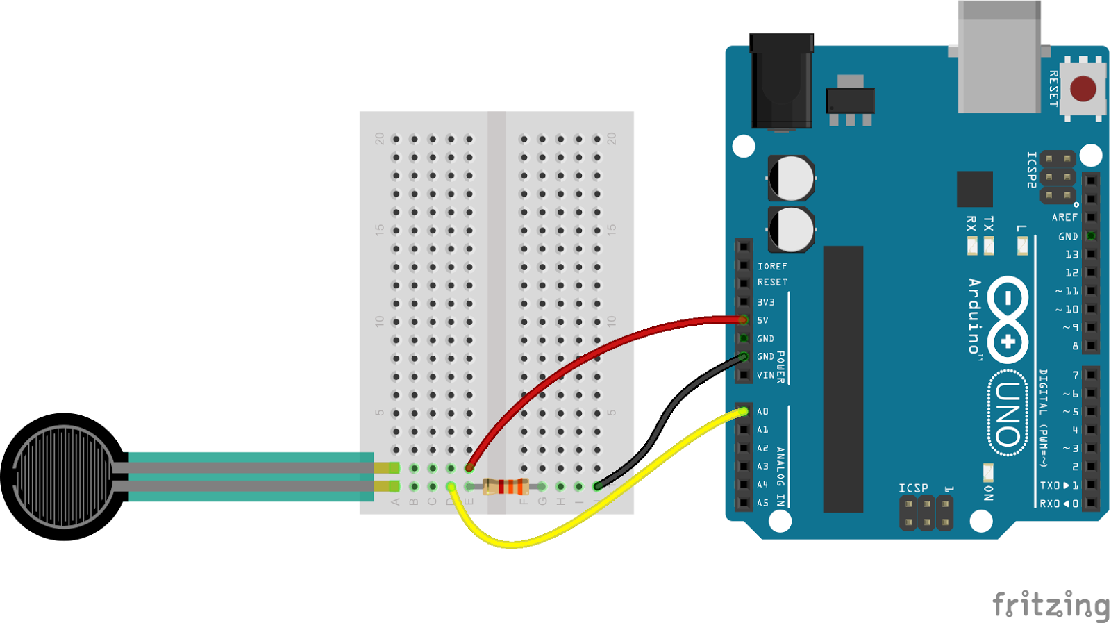
(https://learn.sparkfun.com/tutorials/force-sensitive-resistor-hookup-guide)
Awesome! Now, that you got the hardware setup, you need to code the Arduino so it knows what to do with that information.
Before we start coding, we need to do one last hardware setup. We have an input reading but not output that will change with it. For this example, we will use the electroluminescent (EL) wires. In order to do so, just slide the EL shield on top of the arduino and plug the EL wires onto the side will the row of 8 connectors.
Software
In order to code the Arduino, you will need the Arduino software. When you open a new file, or sketch, you'll see that there is already a sort of outline. The setup function comes before the main loop code because it sets up all of the pins so the main code knows how to treat them in the code. The loop function is where you put the main code. As long as the Arduino is powered, it will continue running through the loop code once it has completed the setup. For our hook up guide, I will use our EL_flex code which uses the flex sensor and causes the EL wires to flash. The rate at which they flash will be dictated by the readings from the flex sensor.
Set up:
This is where we tell the Arduino which pins are input and output pins and to open up communication with the computer so you can print readings.
pinMode (pin, mode):
This function tell the Arduino if the pin is an input or output. The pins are numbered on the side (ex: 1,2, A0, A1).
Serial.begin (baud rate):
This opens communication with the computer so you can print readings and other messages onto your laptop monitor. The baud rate is how quickly the Arduino will communicate with your computer. Usually I use either 9600 or 115200.
Declaring variables:
This can be done either before the setup even starts or in the set up. This section might change as you write the main part of the code and you introduce more variables to store values. There are different types of variables which are used for different purposes but for now, we will use int which stands for integer. To declare a variable, all you need to do is write the type and then the name of the variable right after. The name can be anything you want, but choose a name that makes sense so you know exactly what the value stored in it means. Example: int flex.
Loop:
This is where you need to write instructions for the program to do exactly what you want. While coding, it has helped me a lot to remind myself that the computer isn't the smartest when it comes to figuring out how to accomplish a task. Therefore, you will have to tell it exactly what to do. In this particular example, we want to use the flex sensor reading to change the rate at which the EL wires flash. The steps would look something like this:
- Get the reading from the sensor
- Somehow map the reading from the sensor to a time
- Turn the lights on
- Wait for the time calculated from the sensor reading
- Turn the light off
- Repeat for all wires
Each of the steps above require a coding function. These are listed below in respective order:
- analogRead(sensor_pin): gives you the reading from the sensor. You can manually input the pin name or you can create a constant integer variable (const int) and store the pin name in there.
- map(value, fromLow, fromHigh, toLow, toHigh): This is how we get a time from the sensor readings. The map function essentially creates a proportion which then scales the sensor reading to an appropriate time. fromLow / fromHigh are the minimum and maximum values of the sensor readings respectively. toLow / toHigh are the minimum and maximum values of the desired delay times. You can pick any values you want as the min and max but remember the delay time is in milliseconds (ex: 1 second = 1000).
- digitalWrite (pin, HIGH): This turns the EL wire on. HIGH indicates there is voltage. The pin is the digital pin that the EL wire is connected to. The shield connects the wires to digital pins 2 to 9.
- Delay(milliseconds): This function literally pauses the function for the amount of time specified. Since we want the delay time to change with the sensor reading, the result of the map function (step 2) should go here. The best way to do this would be to assign the result of step 2 to a variable and type in the name of the variable in between the parentheses of the delay function.
- digitalWrite (pin, LOW): This is very similar to step 3 except instead of turning the wire on, we are turning it off. Therefore, we write the pin LOW.
- For (initialization; condition; increment): Now we have one El wire turning on and off, but we want to be able to cycle through all 8 wires. In order to do this, we will introduce a for loop. This loop needs three parameters in order to know what to do. The first parameter is the initial condition. In our case the initial condition is i =2, in which i is a variable representing the pin number (in other words, start on pin 2). The second parameter is a condition, in our case i <= 9. As long as this condition is true, the code will run through the loop. So as long as the pin number, i, is less than or equal to 9, it will loop again. The third parameter is an incrementation. This occurs after a loop is completed and keep count of how many times the loop has run. Our code has (i++) written which means i will increment by 1 (after the first run, i = 2+1). This is how we cycle through each EL wire. The functions described in steps 3 -5 is what goes in the for loop. This is the code that is executed each time the condition is met.
One last function that will be extremely useful. Serial.print() allows you to print a value to the monitor (Tool > Serial Monitor). I use this in order to get the minimum and maximum readings from the sensors. The min and max readings can vary each time you use them, so it is useful to check. In order to do so, use Serial.print(sensor_reading) where sensor_reading is a variable that stores the value of step 1.
Just a little more
Remember, we said the flex sensor and pressure sensors are similar and could therefore be interchangeable (just don't forget to check the min and max values). This is just one way you can play around and alter the tech to match your needs. As you explore our project, you will realize that there is a lot of flexibility in the hardware and code. A lot of the concepts you will need to know in order to implement different sensors and outputs are outlined in this how-to and hopefully it will be useful even when you experiment with other sensors or functions. In case you want to know how to do more with the code the Arduino website has a list of commonly used functions and explains how to use them in a similar way I just did. In terms of sensors, many of them are similar to the flex and pressure sensors in that they will require power, ground, and provide a reading. Keeping this in mind, it is definitely possible to play around with sensors in order to have your project react to different actions.
Example Code
/*
*This code controls the amount of time each EL wire remains on
*EL channels start on pin 2
*example code
*/
//DECLARE VARIABLES
const int sensorPin = A0;
int i;
int delay_time;
int flex;
int delay_time;

void setup() {
  /*
  * Initialize the EL pins as OUTPUTS
  * Initialize the sensor pin as INPUT
  */
  pinMode(sensorPin,INPUT);
  pinMode(2, OUTPUT);  // channel A
  pinMode(3, OUTPUT);  // channel B
  pinMode(4, OUTPUT);  // channel C
  pinMode(5, OUTPUT);  // channel D
  pinMode(6, OUTPUT);  // channel E
  pinMode(7, OUTPUT);  // channel F
  pinMode(8, OUTPUT);  // channel G
  pinMode(9, OUTPUT);  // channel H
  Serial.begin(9600);
}

void loop() {
  /*
  * This code will run in an infinite loop
  * Read each sensor and map voltage from 0-5V to 0-1023 bits
  */
  flex = analogRead(sensorPin); //step 1
  Serial.println(flex);
  delay_time = map(flex,40,100,1000,100); //step 2
  for (i=2; <=3; i++) //step 6
  {
     digitalWrite(i, HIGH);   // step 3
     delay(delay_time);       // step 4
     digitalWrite(i, LOW);    // step 5
  }
}