Unit 3: Analog Inputs and Outputs
Potentiometer (Variable Resistors): Will act like resistors in that they limit the amount of current flowing, however their resistance can change by turning the knob.
Pressure Sensor: Similar to a potentiometer, resistance changes depending on how hard it is pressed.
Circuit 5: LED, Potentiometer
Now we will create a circuit that consists of an LED and potentiometer in order to dim the LED. Similar to the pushbutton and LED, there are two different ways to dim the LED: one that only uses wires and one that requires coding. First we will use just wires in order to understand just what a potentiometer does.
Wire the circuit below. Notice that the potentiometer has three legs. The outer legs are used for power and ground while the middle is used as an input. This means that the value coming out of the third leg will change depending on how far the knob is turned. Pay attention to which wires are connected to which legs.

Now experiment by turning the knob clockwise and counterclockwise. What happens? If the potentiometer acts as a resistor and voltage is consistent, what determines how bright the LED is? (Hint: V = I * R).
Circuit 6: LED, Potentiometer with Arduino
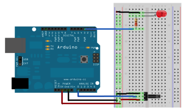
Now that we are familiar with the potentiometer, we can use it as an input to our code. Unlike the pushbutton that only had two values (on and off) the potentiometer has many different readings. This is an analog input and therefore uses the analog pins. Wire the circuit below, and once again pay close attention to which pins are connected to which legs.
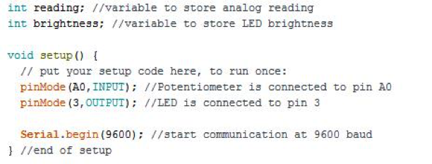
For the code, we will need to tell the Arduino which pins are inputs and which are outputs. If you remember from the lessons before, the pins are automatically set to input, so technically we don't need to have the line declaring the analog input, but I put it in out of habit. We will also need to set up a variable to store the reading from the potentiometer.
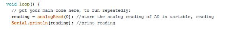
Now we need to read the value coming from the potentiometer. Similar to how we used digitalRead to read a digital value from the push button, we will use analogRead(pin) to read the value from the potentiometer. This value is representative of the amount of voltage in the potentiometer. If we print this value to the Serial Monitor, we should be able to see the readings change as we turn the knob. Don't forget to store this value in the variable we created above.
Notice the minimum and maximum values coming from the potentiometer. Even though the maximum amount of voltage possible is 5V, there is a reading of 1023. This is because the voltage is expressed on a scale of 0 - 1023. In order to calculate the voltage coming from the potentiometer, set up a proportion and solve. The proportion is as follows:
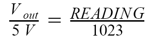
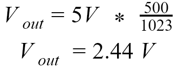
So if you were to have a reading of 500, the equation for Vout would be:
Since we have our readings, we need a way to convert it to a brightness value for the LED. By using analogWrite(pin, value) we can tell the LED how bright to be. analogWrite only works on pins 3, 5, 6, 9, 10, and 11 on the Arduino Uno so make sure your LED is connected to one of these pins. These pins are indicated by a squiggle line next to the pin.
We are almost reading to use analogWrite, but we don't have a value to write to the LED pin. analogWrite can use values between 0 - 255, so we can't directly use the value we recorded from the analogRead command. Instead, we will use the map(value, fromLow, fromHigh, toLow, toHIgh) function in order to scale the value read from the potentiometer. The map function requires four parameters: the value (the reading from the potentiometer), the minimum value of original range, the maximum value of the original scale, the minimum value of the new scale, and the maximum value of the new scale. The function then creates a linear relationship, y = m*x + b where (y) is the new value, (x) is the old value, (m) is the appropriate proportion, and (b) accounts for different minimum values. The general equation is as follows:
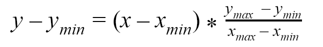
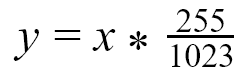
So if we were to apply this to our example, xmin=0, xmax=1023, ymin=0, ymax=255:
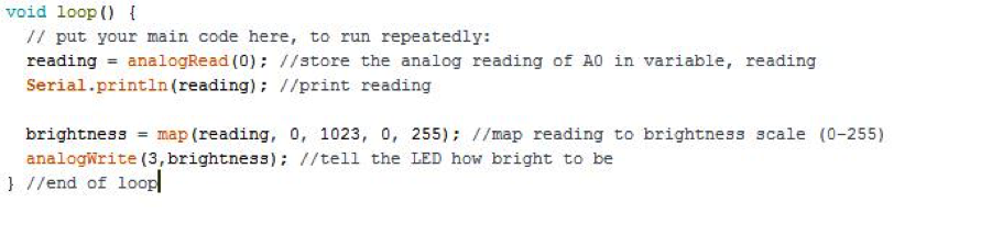
Now we can store this value in a new variable and use the analogWrite function as shown below.
Circuit 7: LED, Pressure Sensor
In this section, we will replace the potentiometer with a pressure sensor. You'll notice the pressure sensor only has two legs instead of three like the potentiometer. This will require a slightly different setup that creates a voltage divider. A voltage divider is a specific type of circuit in which two resistors are wired in series like shown below
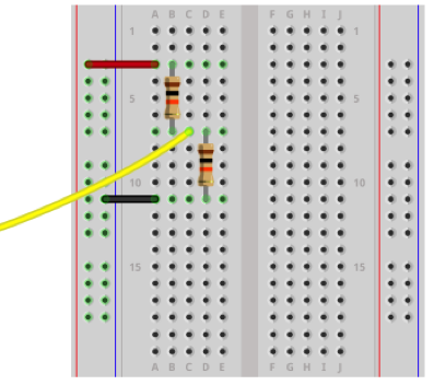
The voltage is then divided proportionally between the two resistors. By reading the voltage in between the two resistors (the yellow wire above), you are measuring the voltage going to the second resistor. The general equation is as follows:
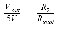
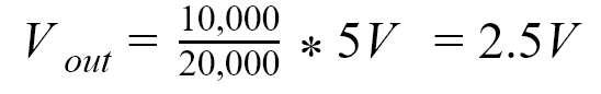
So if you have the setup shown above where R1=10,000 Ohms,R2=10,000 Ohms,and Rtotal=R1+ R2:
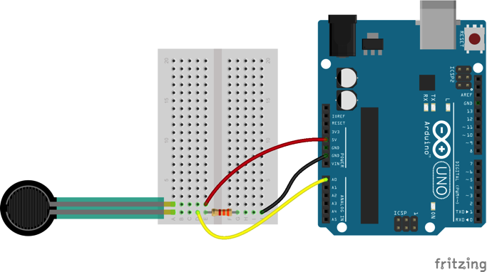
Now, when we replace the second resistor with a pressure sensor as shown in the diagram below, the voltage reading should change depending on the resistance of the sensor. Even though the diagram below does not show it, keep the LED wired on your breadboard.
Open a different sketch and quickly take a reading from the analog pin you are connected to.

Observe the minimum and maximum values (these will be important later). What do you think will happen if you change the value of the first resistor? If you want, experiment with different values by replacing your current resistor with one that is significantly higher or lower. What happened? Return to your original resistor and record the minimum and maximum values. Go back to the sketch that dims the LED and use these values in the map function as the minimum and maximum values for the original scale. Now re-upload your code and observe what happens when you press the pressure sensor.
Questions:
- How does the resistance of the pressure sensor change as you press it? Does it get higher or lower? (Hint: look at the voltage divider equation and the analog readings you print).