Unit 4: And More...
Flex Sensor: Act like potentiometers, resistance changes when it bends.
Circuit 8: 2 LEDs, Flex Sensor
The flex sensor has a similar setup as the pressure sensor. Since the hardware components are so similar, this example will just introduce more coding functions. The goal of this system is to control the rate at which the LEDs flash using the flex sensor. First, wire the flex as shown below:
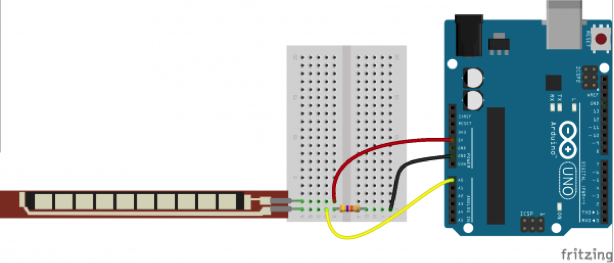
It's a good idea to check the minimum and maximum values coming from A0 as we will use these values later.
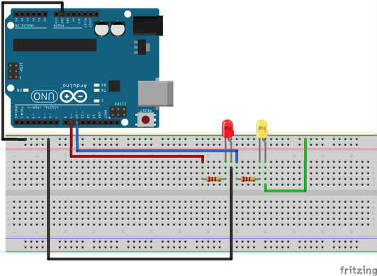
Now add the two LEDs onto the breadboard and connect them to two different digital pins as shown below:
The setup in the code should look something like this:
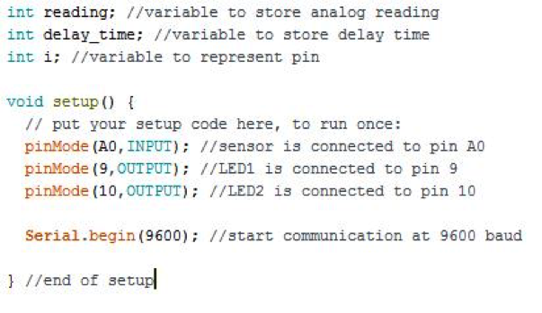
NOTE: So far I've been telling you when to create variables, but remember you can use variables to store any value you think might be useful later or you can add more variables as you develop your code.
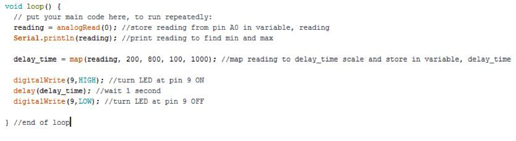
For now, we will focus on turning a single LED on then off. Remember from the previous lesson that in order to do this, we need to write the pin HIGH then LOW. However, if we do this the LED will turn on and off so quickly we won't notice it. In order to make the blink more noticeable we need to add a delay(time). The delay will pause the code for the specified time in the parentheses. Keep in mind the time is in milliseconds (i.e. 1 second = 1000). We want our time to vary depending on the reading from the flex sensor, therefore we need to add a map function which maps the reading from the sensor to a time. The original minimum and maximum values from the sensor are the ones found by printing out the analog readings and bending the flex sensor. The minimum and maximum times are up to you, but in this example I use 0.1 seconds as the minimum and 1 second as the maximum.
That turns one LED on and off, but what if we wanted to control more than one? For this we will use a for(initial, condition, increment) loop. The for loop requires three parameters: the starting value, a condition that must be met, and a increment. For example, if I want to start off at pin 2, I will create a variable that represents the pin number I am currently controlling. In this case, the variable is a lowercase i. The initial value will then be 2. The condition is as long as the pin number is less than 4 and the increment will be add one. So as long as the pin number is less than 4, it will execute the code in the loop. The code in the loop will be the code we wrote above which turns the LED on and off.
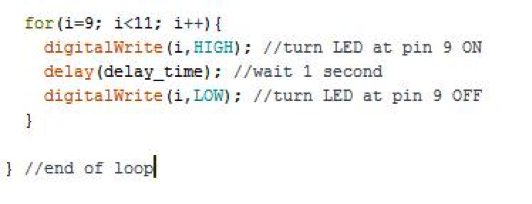
Now you should see your LEDs flashing back and forth with a speed varying with the flex sensor. If you want to wire up more LEDs, the only part you will have to change in the code is the condition, which should then allow the pin number to go above 4.
To discover different applications of other sensors, see the DIY photogate project on the CSDT website. This project uses a photoresistor in order to detect light and applies some concepts you have learned in this how-to to sports.