Unit 1: Introduction
In this exercise you will simply light up an LED (Light Emitting Diode). Although that is a very simple circuit, it will give you a chance to learn the following:
- How to get power from an Arduino
- How to use a breadboard
- How to read values from a resistor
- How to use Ohm's law to calculate resistance
- How to use an LED
Arduino:
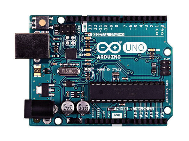
The Arduino is a microcontroller which stores a set of instructions that allows the board to take in inputs and produce the desired outputs. Often the Arduino powers the circuit you are using as well. All circuits have electrons flowing from the negative terminal or “ground” to the positive terminal. For these exercises, we will be using the Arduino as a main power source. As indicated in the picture above, the Arduino can supply a positive voltage of either 3.3V or 5V. These are indicated both on the board as well as on the side of the terminal, or pin. There are also three ground pins labeled as GND.
In addition to power and ground, the Arduino has digital and analog pins that can take in information such as data from sensors, and send out signals to motors or other effectors.
Breadboard:
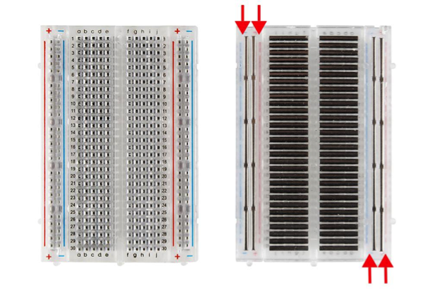
The breadboard is a great way to quickly build and test circuits. The diagram shows you what a breadboard usually looks like as well as what goes on underneath the plastic. As the diagram shows, the middle rows are connected by short horizontal metal strips, while the end two columns are connected by longer metal strips. The end two columns are commonly used for power and ground. Power is usually indicated by red or some other “hot” color, and ground is usually black or some other “cold” color.
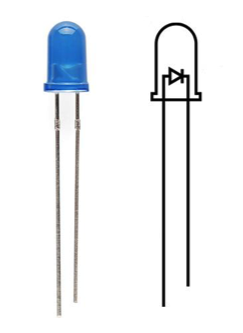
Light Emitting diode (LED):
These convert electrical energy into light. Current will only flow in one direction, so if your LED isn't working try turning it around. The longer end must be connected to power, and the shorter end to ground. Past a certain voltage, the LED will start taking in more and more power, until it burns out. So to prevent that we need a current limiting resistor. Usually a good value for that is 100 Ohms, but if you want to learn a bit more, we can calculate that in the next section.
Resistors:
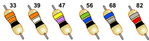
Resistors are electrical components that serve to limit the flow of electricity through a circuit. The amount of resistance is measured in Ohms. The larger the resistance, the more current it can block. Usually the resistance is represented by three colored bands, plus a 4th gold or silver band at the end to indicate precision. which will represent the value of the resistor. The first two strips will be digits, the third will be the “multiplier” (an exponent of 10). The chart below briefly illustrates this and demonstrates which color represents which digit.

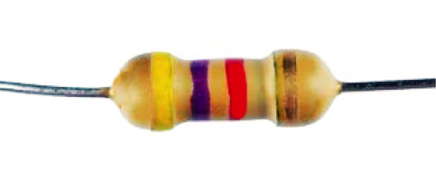
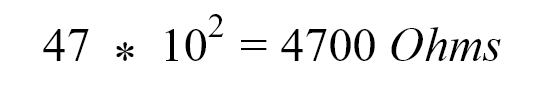
For example, the first two digits of the resistor above are 4 (yellow) and 7 (violet). The third band (red) tells you to multiply this number by 102 so you end up with:
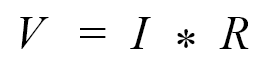
You can think of the electricity flowing like water in a hose. The resistor is the diameter of the hose, the voltage is the water pressure, and the current is rate of water flow. The smaller the hose diameter, the more pressure would be required to achieve the same flow rate. This relationship holds for electricity as well: in the equation below V is voltage (volts), I is current (amps), and R is resistance (Ohms).
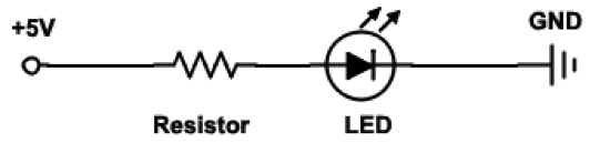
You can use this equation to calculate the current running through the LED. Here is our circuit.
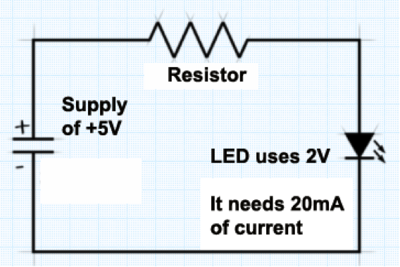
In this case the , use the resistance we calculated above (R = 4700 Ohms), and assume the LED uses 2V to turn on. The supply voltage Vs is 5V, so the remaining voltage drop across the resistor VR is 3V:
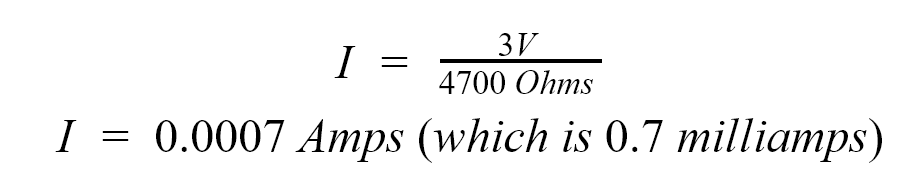
Only 0.7mA is probably not enough to turn the LED on. Usually, 20 milliamps is the right current that would result in maximum brightness for red LEDs. Using this information, we can calculate the value of the resistor we will need (remember 20 milliamps = 20 * 103 ).
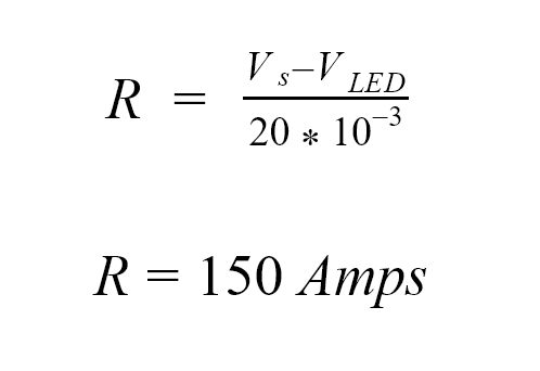
Resistors come in standard values, and a 100 Ohm resistor (brown black brown) is probably the closest you can find to 150 Ohm. You can increase or decrease the resistor value depending on if you want the LED dimmer or brighter respectively. Resistors in series will add their values. For resistors in parallel, add their inverses and then invert that sum. For example two 10 Ohm resistors will be the inverse of 1/10+1/10, which is 10/2.
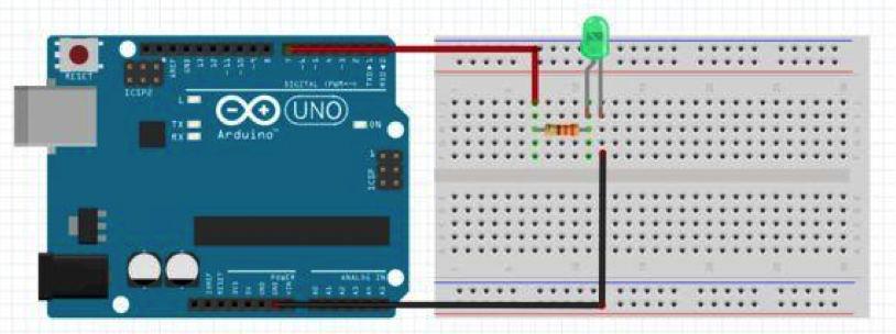
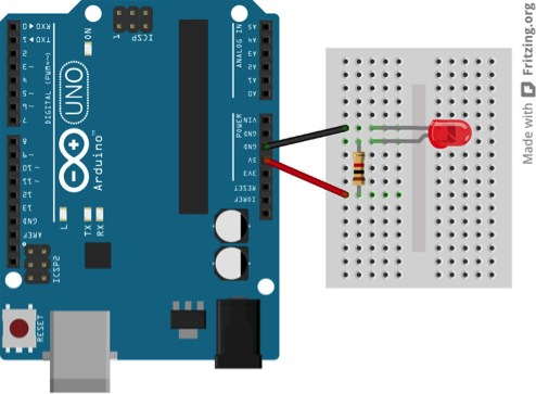
Circuit 1: Lighting up an LED
This example will be a simple circuit that will get you acquainted with using a breadboard. The circuit you will be wiring will consist of a single LED and one resistor. The short end will be connected to ground while the longer end will be wired to a resistor and power as shown below. First, we will show you how to wire the circuit without the use of any code. Then we will show you a similar, but slightly different circuit that utilizes the Arduino code. Wire the circuit below, but connect the RED WIRE to the 5V PIN.. Don't forget the resistor or you might burn out your LED. Connect the Arduino to your computer and the LED should light up.
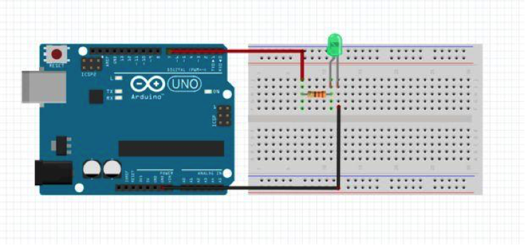
Circuit 2: Lighting up an LED with Arduino
This circuit will now acquaint you with the Arduino software. Now, we will move the red wire to pin 7 as shown below and light up the LED using a simple code.
Open the Arduino software if you have not done so yet. When you first open a new sketch in Arduino you should see something like this:
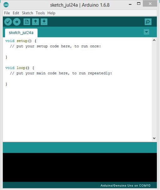
There are two main functions: the setup and the loop. The grey text, or comments, below each function tells you what the function does. The setup can be used to tell the Arduino which pins are inputs and outputs and will only run once. The loop function is where the main code will go and will run repeatedly. If the text is colored grey, it is a comment and will have no effect on the functionality of the code. This is used mainly for humans so you and other people will know what the code is supposed to do. In order to make a line of code a comment, put two backslashes (//) at the front of the line. When your code is finished, the check mark will check your code for any errors and the arrow pointing sideways will upload your code to the Arduino.
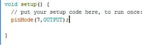
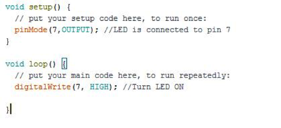
As mentioned before, the setup is where you tell the Arduino which pins are outputs and inputs. Pins on the Arduino are by default input pins, however in the circuit you just created, there is not inputs and one output. An output is something that is controlled by the Arduino (like a motor or light) while an input is a signal that tells the Arduino about some event (like a switch or sensor). Whether the LED is on or off depends on the Arduino therefore it is an output. In order to tell the Arduino this, you type in pinMode(pin, OUTPUT), where pin is the number pin the long side of your LED is connected to.
Now that the Arduino knows there is an output at that pin, it will supply the pin with power which will then travel along the metal and should turn on the LED. In order to turn the LED on and off, we will use digitalWrite(pin, state). The pin is the pin number the LED is connected to and the state is HIGH in order to turn it on and OFF in order to turn it off. The end code should look something like this. Upload and see if your LED turns on.
Questions:
- Turn the LED around so the short end is connected to the power and the long end is connected to ground. What happens? Why do you think that is? (Hint: google search what a diode is).
- *DO NOT DO THIS* Hypothetically if you were to take the resistor out, the LED would burn out. Why do you think this would happen? (Hint: look back at the function of a resistor).